SB CAN TH
1. Introduction
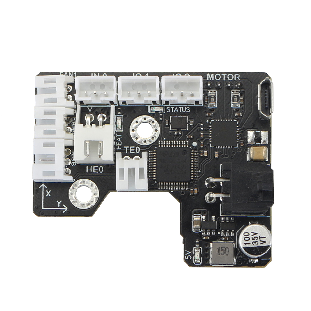
The SB CAN Tool Board is a highly integrated printhead control board. Based on STM32F072, running Klipper firmware. Onboard TMC2209 stepper motor driver, AXL345 acceleration sensor, and other necessary interfaces. And comes with a 2.5m 4-core cable for easy out-of-the-box use.
1.1 Feature
-
Based on STM32F072
-
Onboard 1M CAN transceiver
-
Onboard TMC2209
-
2x 0.5A MAX PWM interface for controllable fan (default VIN power supply, 5V optional)
-
1x signal input interface (VIN power supply, with level conversion)
-
2x signal input and output interface (5V power supply, with pull-up resistor)
-
1X 5V single wire RGB interface (1A MAX)
-
1x 4A MAX PWM output for heating rod
-
1x ADC interface for heating rod temperature acquisition
-
MX3.0 2X2 interface for power and CAN signal access
-
1x Micro USB for firmware uploading
-
Comes with 2.5m 4-core cable, 2x16AWG+2x24AWG
-
Comes with terminal housing and wire crimping tabs
2. Hardware Guide
2.1 Install
Before you install the board, you need printed parts here. Then follow the 5 steps below.
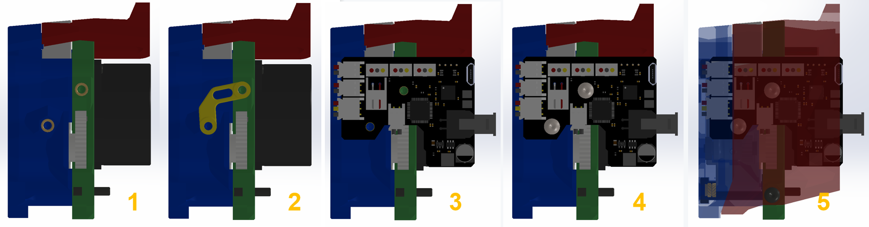
- You Stealburner should have to holes with heat inserts on.
- 3D Print the pcb_spacer.STL
- Place the PCB on the position
- Screw it to printed head and pcb_spacer.STL
- Follow the chapter
2.2 wiringto connect the peripherals and cover the lid.
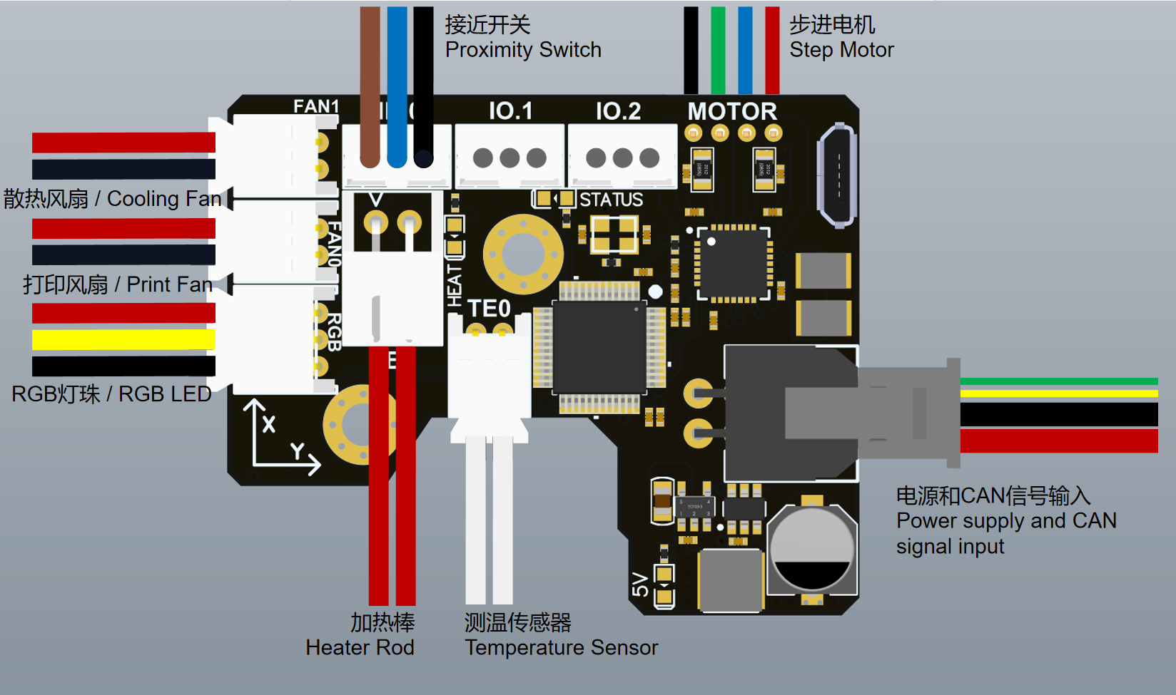
2.2 Connectors
| Connector name | Type | Details |
|---|---|---|
| IO.2 | PH2.0-3P | PB7,for input and output, hardware pull-up 10k resistor to 3.3v with 1k series resistor. Example: endstops |
| IO.1 | PH2.0-3P | PB11,for input and output, hardware pull-up 10k resistor to 3.3v with 1k series resistor. Example: endstops |
| IN.0 | PH2.0-3P | PB6,default 24v with level translator, pull-up to 3.3v |
| MOTOR | PH2.0-4P | TMC2209 EN : PB4 DIR : PA5 STEP : PA7 SPREAD : PA15 DIAG : PB5 INDEX : PB3 RX : PA10 TX : PA9 |
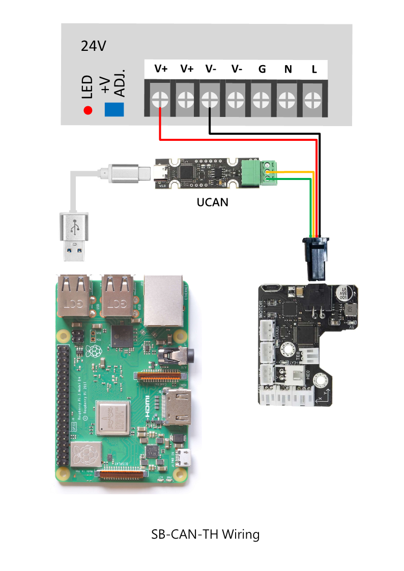
| INPUT | MX3.0 2X2P | Max 24v 5A input(16AWG)/CANL,CANH (24AWG) |
| TE0 | PH2.0-2P | PA0,ADC,4.7K pull-up to 3.3V |
| HE0 | XH2.54-2P | PA8,MAX 4A,PWM output,max power recommended: 60W |
| FAN0 | PH2.0-2P | PA2,0.5A MAX PWM,for fan control (default VIN,5V selectable) |
| FAN1 | PH2.0-2P | PA3,0.5A MAX PWM,for fan control ( defalt VIN,5V selectable ) |
| RGB | PH2.0-3P | PB1,1A MAX sigal line RGB port, 5V,for NeoPixel, WS2812 |
| Micro-USB | For firmware update and USB communication. Firmware update: Plug in USB first then power on. USB communication: Power on first then plug in USB port |
2.3 Wiring
2.4 SCH DXF STEP
Get SCH, DXF, STEP files on github:
GitHub - FYSETC/FYSETC_SB_CAN_TOOLHEAD: StealthBurner toolhead CAN bus module for VORON
3. Firmware Guide
This is only Klipper firmware support. If you are Klipper beginner please check the Klipper firmware build here: Installation - Klipper documentation
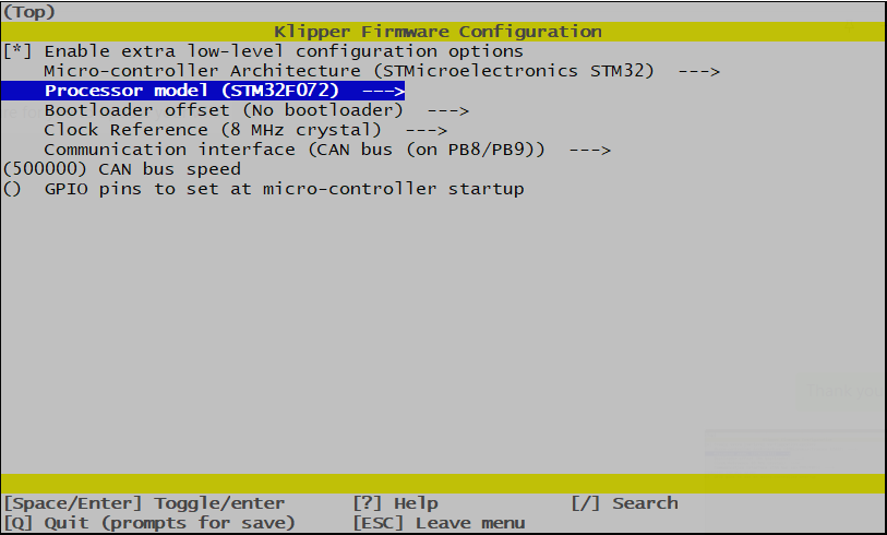
3.1 menuconfig
3.2 Firmware Upload
There is Micro-USB port on the board for firmware upload. Follow the sequence below.
-
Power on your machine and wait for raspberrypi (Or other SBC) ready.
-
Power down SB-CAN-TH board for at least 5s
-
Connect SB-CAN-TH Micro-USB to RaspberryPi USB-A port with USB cable
-
Plug in SB-CAN-TH board 24v socket to power on it( Get the power from machine PSU)
-
Shoot
lsusbcommand in Raspberry to check if it shows DFU port, if not go back to step 1 -
Shoot command
dfu-util -R -a 0 -s 0x08000000:leave -D out/klipper.bin -
Remove Micro-USB cable and SB-CAN-TH socket for 5s, then plug in SB-CAN-TH socket again.
-
Finished
3.3 Configuration
Obtain the Klipper configuration file here , you need to get the CAN ID following CANBUS - Klipper documentation:
4. Log and known issues
4.1 v1.1
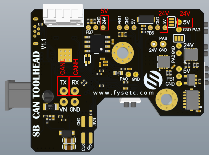
Note: v1.1 have some silk print errors below, the red letters are the right silk print.
Buy
Contacts
QQ:1041794121
Facebook小组:https://www.facebook.com/groups/197476557529090
Discord频道:https://discord.gg/Fb6FdND4